Tuesday, November 10, 2015

Civil 3D ALIGNMENTS (Basics) PART 1


Hi, I will be discussing for this post are Alignments. What are Alignments and What are their use in Civil 3D and Highway Design.

What are Alignments?
Based on the Civil 3D HelpAlignment objects can represent road centerlines, pipe networks, and other construction baselines.

Alignments are Lines, Polylines or Splines that represent a Construction Baseline in a TOP VIEW / PLAN VIEW. Please see the Image for a example on where to use Alignment as Parts of a Road

Please do note that Alignments doesn't have any Elevations or Z Value. you would need to make a Vertical Profile to Assign Elevations to it. (which I will be discussing in my future post.)

Creating a Alignment:
1.) A simple approach is to use a Polyline in creating a alignment. I would first create a Polyline in my preferred location may it be the centerline of the road or the edge of pavement and then convert it into a Alignment. It would depend on the Highway Design Engineer to decide where to make the alignment.

2.) Another approach in creating a alignment is by drawing it PI to PI (Point of Intersection). Which is my preferred approach if I am Designing a new Road/Highway.

Before Continuing please make sure you have done the Exercises in the Rough or Smooth Surface Post. Since we will be using the same drawing. Especially the Exercise number 3.


Let's Start with the Exercise.
The Project is a Simple Widening Project in San Fernando, Pampanga, Philippines. After Countless meetings with the Client and Local Officials we have drawn to a conclusion to Convert the two Roundabouts to two Signalized intersection and widen the existing "two/three lane, two direction" to "four lane, two direction" Please see Image of the Existing Project Location.

Please see Image of the Proposed Configuration made by me. (which is based on the AASHTO design standard)

for the drawing files. You can download the Existing Layout here and for the Proposed Configuration you can download it here.

Exercise 1 Using Polylines.
1.) Open the FINAL LAYOUT.dwg you downloaded before and paste all the contents in a new drawing using the basic template _AutoCAD Civil 3D (Metric) NCS. you should have a drawing like the image below. (Note: when Copying, Use a Copy with Base point command with a base point at 0,0,0 to make sure the objects stays at the same location.)

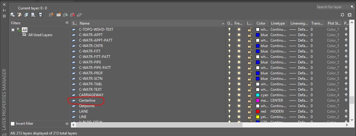
2.) Make a Layer name it "Centerline" Choose any color and line type. (as for me I will be using Magenta as my color and Center as my line type.) Please see Image below.

3.) Based on the Drawing there is a median in the Center with a 1.7m width. Offset the yellow line by 0.85m to get the center. layer it as "Centerline" which we have made in step 2. You should have the something like the image below.

4.) Do this until you make a Line - Curve - Line  located at the center of the median. which the Curve should have a radius of 500m. See the Image. (make sure to make it as a Polyline.)

5.) From the Ribbon > Click Alignment > Click Alignment From Objects. (Please see Image Below.)

6.) You will be asked to select the Object you want to make as basis for the Alignment. Select the Polyline we just created. You will be then asked if the desired direction is ok or you want to reverse the direction. pick any. Since there is a option to reverse it later if we want to.

7.) A "Create Alignment from Objects" Dialog Box will appear. Change the Name to whatever your comfortable with. I will be using Main as my Alignment name. Leave all items as default but make sure to uncheck the "add curves between tangents." and "Erase Existing Entities.". Please see the image.

8.) Click Ok and we're done with the 1st exercise.

Creating Polylines with Create Alignment Layout tools will be discussed on the next post. which is my proposed approach when designing new roads and highways.

Thank you. :)

Thursday, November 5, 2015

Rough or Smooth Surface (Part 2)


I suggest before reading this 2nd Part. Please do read and do the exercise in Part 1 of this Post.

So here is the Part 2 of the Rough or Smooth Surface Post.

In Part 1 we discussed what is a surface and how to make one in Civil 3D using COGO points in a Drawing.

In here we will be discussing how to make a Surface using Polylines as Contours and how to Import a LandXml to produce a Clean Surface made by a Surveyor.

So Let's Begin with the Exercise.
B.) Using Polylines as Contours in a Surface. (Please download the Drawing file here which contains the Contours to be used.)
b1.) Open the Drawing file and Copy all the Objects in that Drawing to a fresh new Civil 3D drawing. You can use the Standard Template in Civil 3D "_Autocad Civil 3D (Metric) NCS"

b2.) Make a new surface which was Discussed in the Part 1 of this Post. Expand the "EXISTING TOPO" > Expand "Definition" > Right Click "Contours" > Click "Add.." (Please see Image)
b3.) You should see a "Add Contour Data" Dialog Box. A good practice in using this is to Input a Description. I always use the Date when the Topographic Survey was provided to me. (Please see Image.)
b4.) And we're Done. (Please see Image.) to Appreciate it you could go to Object Viewer Discussed in Part 1. (Please see Image 2 for a Conceptual View of the Surface.)


C.) Importing LandXml file to Duplicate a Clean Surface made by a Surveyor. (Please download the LandXml file here.)
c1.) Open a Civil 3D drawing using the standard "_Autocad Civil 3D (Metric) NCS" template
c2.) On the Ribbon, Go to Insert Tab. You should be able to see a LandXml Button there. Click it. (Please see Image.)
c3.) Browse and Select the LandXml file you downloaded.
c4.) You should be able to see a "Import LANDXML" Dialog Box. Click Ok. (note: if the LandXml File contains many Civil 3D Objects. You can just select which Object you want to Import. I will discuss this in a future Post.)
c5.) And we're Done. (Please see Images)


So what is the difference between the three methods posted?
When using Points you can get those small elevation difference but a dirty looking surface will be produce. Which would still need some Cleaning.
When using Polylines, You would only get an approximate elevation since Contours have Intervals. You may request a smaller Interval like .1m and .5m Interval for a more accurate Surface.
When using LandXml, It is the same with Points but already Cleaned out by the surveyor. See the Image in step "c5" you could really imagine what the actual project location looks like.

If you are going to ask me, I would ask for a LandXml File from the Surveyors. If in some way they can't give it to you, I would ask for Points/Point file and clean the Surface myself (in which I would discuss in a future post). and in the worst case scenario. I would use the Polylines.

for any Comments or Questions please feel free to Contact me.


Tuesday, November 3, 2015

Rough or Smooth SURFACE (part 1)


So what are Surfaces?

Based on the Dictionary,

Surface is the Outside part or uppermost layer of something (often used when describing its texture, form, or extent).

Based on the Civil 3D help,

Surface  is a three-dimensional geometric representation of an area of land, or, in the case of volume surfaces, is a difference or composite between two surface areas.

So to simply put it, Surface in Civil 3D represents the Survey data from Engineering Surveyors or the final shape or form of your Design.


I am assuming right now you have read my previous post, which is Points here, Points there. If not, I would recommend you to read it and do the exercise given there. Here is the Link.


Types of Files a Surveyor may provide for a Poject:

1.) Point File: I have discussed this on my previous post. again, Here is the Link. But in here I will be discussing on how to use them to generate a Surface.
2.) Polyline: Engineering Surveyors may provide their data as Contours or Polylines with elevations (Z value) in a dwg Format. The only downside I can see from this type of file is that Contours have certain interval such as 1m (Minor) and 5m (Major). In which you would be missing the elevations between those interval. I will be showing the difference later.
3.) LandXml: My favourite type of file. Engineering Surveyors who used Civil 3D in inputting their survey data are most likely to have generated their Surface already. In which they have already Cleaned it up (I may be discussing in a future post). Surveyors may give this type of file which is the direct copy of their generated Surface. another good thing about this is that you can easily import them in any Civil 3D drawings.

So Let's Begin with the Exercise in Creating a Surface.

A.) Point File:
a1.) Open the file used in the Previous Post Points Here, Points there. You should be seeing the Image below.

a2) In the TOOLSPACE, Right Click Surface and Select Create New Surface. (If you accidentally closed TOOLSPACE, You can open it by going to the Home Tab in the Ribbon and Click TOOLSPACE.)

a3.) A Create Surface Dialog Box will appear. for the name, Input "EXISTING TOPO" or any name you want. For style, you can choose what Contour Interval will be shown and for the Render Material, you can Pick any Presets given there. since you will only be seeing the difference if you would just look at it in a REALISTIC visual style. (in which I may also be discussing in a future Post)
a4.) In the TOOLSPACE, You should be able to see the EXISTING TOPO under the Surface tab. Expand the EXISTING TOPO > Expand the Definition > In here you should be able to see what types of files you can input in the surface. > You can choose Point File or Point Group, But we will go with Point Group for this Exercise. > Right Click Point Group and click Add.
a5.) A Point Groups Dialog Box will appear. Select _All Points then click Ok.
a6.) You should be able to see the image below. For a better view, you can click the surface and right click anywhere in the drawing. Select Object Viewer.

a7.) in the Object viewer go to Conceptual View and Rotate it as you Like.
And were Done with Creating Surface using Point File.

I will be Discussing the Part two of this Post Later this week. Which will include the using Polylines and LandXml for Surface Generation.

Part 2 is already up, Please go to this Link.

Sunday, November 1, 2015

Points Here, Points There.


Points are the first things you should know when using Civil 3D.

So what are Points created in Civil 3D? are they different from the Points created in Autocad?

Points Created in Autocad contains only the coordinate data (XYZ), while Points created in Civil 3D contains different information such as Point number, Point Description and the coordinate data (XYZ). This Points are called COGO (Coordinate Geometry) Points. Good thing about COGO points is that they can be referenced, Placed outside the drawing and be used by different Users.

So Let's do a small Exercise in Using COGO Points.

Importing COGO Points:

When starting a Project, The first thing you would need is a Topographic Survey. There are Different ways a Engineering Surveyor would give you a Topographic Survey but for this exercise we would assume the survey was given as a Point File in .CSV format.

You can Download the CSV file here

Once Downloaded, here are the steps to input the file in Civil 3D
1.) Inspect the CSV file.
As seen in the CSV file the first Column is the Point number, 2nd is the Northing, 3rd is the Easting, 4th is the Z value or elevation. (Please see Image)
2.) after Inspecting the CSV file, Open Civil 3D. Use the Standard Template "_AutoCad Civil 3D (Metric) NCS" (Please see Image)

3.) In The Home Ribbon, Click Points>Point Creation Tools. A Create Point Dialog Box will appear. Select the Import Points Button. (Please see Image)

4.) After Clicking the Import Points Button, a Import Points Dialog Box will appear. Click Add Files Button. (Please see Image)
5.) Browse to where the CSV file downloaded was saved. Open the File.
6.) Specify the Point File Format. Based on our Inspection on Step 1, we will be using PNEZ (Comma Delimited). (Please see Image) then Click "Ok"
7.) A Duplicate Point Number may show if there are existing Points in the Drawing or if the Point file has Duplicate Point Number. I recommend to use Merge as the Resolution if we are not sure about the duplicated Points. (please see image) Click "Ok"
8.) We are Finished with the Exercise. You should be able to see the COGO Points in your Drawings. (Please see image)

You could now use the Points imported to Create a Existing Surface/Terrain. which will be discussed in the Upcoming Posts and the Other features of Civil 3D. Thank You.

Note: For your Reference,The COGO Points used in this exercise are from Actual Engineering Survey done at the San Fernando Interchange NLEX located at City of San Fernando, Pampanga, Philippines.